CSE 120 - Computer Architecture Notes
These are my notes from CSE120 Computer Architecture, taught by Prof. Nath in Winter 2022 quarter. It is based on this book.
Performance
Moore’s Law is the observation that the number of transistors per chip in an economical IC doubles approximately every 18-24 months.
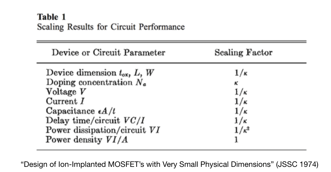
Dennard Scaling(1974) $\to$ observation that voltage and current should be proportional to the linear dimensions of a transistor. As transistors shrank, so did the necessary voltage and curent because power is proportional to the area of the transistor.
- A way of scaling transistor parameters (including voltage) to keep power density constant
- Ignored leakage current (when a transistor is sitting idle, how much current is it leaking) and threshold voltage (minimum amount of voltage needed to turn a transistor on and off, doesn’t scale well past below 65nm), which caused the end of dennard scaling, which has led to flatline in clock speed of CPUs @ ~4.5 GHz.
CPUs haven’t improved much at single core performance, most gains come from having multiple cores, parallelism, speculative prediction, etc, all of which give a performance boost beyond transistor constraints.
Dynamic Power dissipation of $\alpha * C * f * V^2$ where
- $\alpha$ = percent time switch
- $C$ = capacitance
- $f$ = frequency
- $V$ = Voltage
As the size of the transistors shrunk, voltage was reduced which allowed circuits to operate at higher frequencies at the same power.(Intuitively, if both $C$ and $V$ decrease, we can increase $f$)
Latency $\to$ interval between stimulation and response (execution time)
Throughput $\to$ total work done per unit of time (e.g. queries/sec). Throughput = $\frac{1}{Latency}$ when we can’t do tasks in parallel
clock period $\to$ duration of a clock cycle (basic unit of time for computers)
clock frequency $\to$ $\frac{1}{T_p}$ where $T_p$ is the time for one clock period in seconds.
Execution time = $\frac{C_{pp} * C_{ct}}{C_r}$, $C_{pp}$ = Cycles per program, $C_{ct}$ = Clock cycle time, ${C_r}$ = clock rate
- execution time by either increasing clock rate or decreasing the number of clock cycles.
Performance For a machine $A$ running a program $P$ (where higher is faster):
$Perf(A,P) = \frac{1}{Time(A,P)}$
$Perf(A,P) > Perf(B,P) \to Time(A,P) < Time(B, P)$
$\frac{Perf(A,P)}{Perf(B,P)} = \frac{Time(B,P)}{Time(A,P)} = n$, where $A$ is $n$ times faster than B when $n > 1$.
$Speedup = \frac{Time(old)}{Time(new)}$
Little’s Law $\to Parellelism = Throughput * Latency$
- CPU TIME $\to$ the actual time the CPU spends computing for a specific task.
- user cpu time $\to$ the CPU time spent in a program itself
- system CPU time $\to$ The CPU time spent in the operating system performing tasks on behalf of the program.
Clock cycles per instructions(CPI) $\to$ is the average number of clock cycles each instruction takes to execute. We use CPI as an average of all the instructions executed in a program, which accounts for different instructions taking different amounts of time.
- determined by hardware design, different instructions $\to$ different CPI
$CPU\ Time = I_c * CPI * C_{ct}$ where $I_c = $ instruction count and $C_{ct} =$ clock cycle time. $CPU\ Time = \frac{I_c * CPI}{C_r}$ where $C_r$ = clock rate. Clock rate is the inverse of clock cycle time.
Measuring performance of a CPU requires us to know the number of instrutions, the clock cycles per instruction, and the clock cycle time. We can measure instruction count by using software tools that profile the execution, or we can use hardware counters which can record the number of instructions executed. Instruction count depends on the architecture, but not the exact implementation. CPI is much more difficult to measure, because it relies on a wide variety of design details in the computer (like the memory and processor structure), as well as the mix of different instruction types executed in an application. As a result, CPI varies by application, as well as implementations of with the same instruction set.
- Using time as a performative metric is often misleading, and a better alternative is MIPS (million instructions per second) $\to \ \frac{I_c}{Exec_{time} * 10^6}$
- 3 problems with MIPS when comparing MIPS between computers
- can’t compare computers with different instruction sets, because each instruction has varying amounts of capability
- MIPS varies on the same computer depending on the program being run, which means there is no universal MIPS rating for a computer
- Lastly, if a computer executes more instructions, and each instruction is faster, than MIPS can vary independently from performance.
- 3 problems with MIPS when comparing MIPS between computers
Given $n$ processors, $Speedup_n = \frac{T_1}{T_n}$, $T_1 > 1$ is the execution time one one core, $T_n$ is the execution time on $n$ cores.
- $Speedup\ efficiency_n \to Efficiency_n = \frac{Speedup_n}{n}$
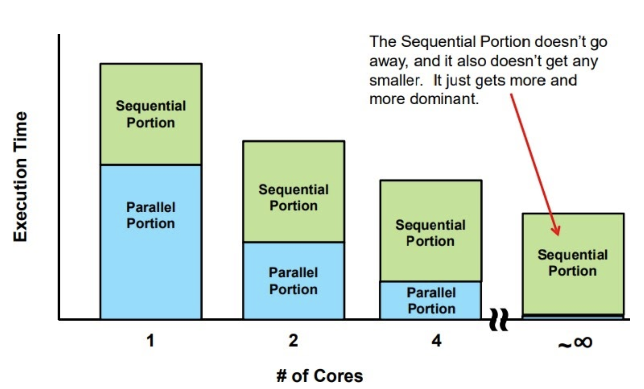
Amdahl’s Law $\to$ a harsh reality for parallel computing.
- $Speedup_n = \frac{T_1}{T_n} = \frac{1}{\frac{F_{parallel}}{n} + F_{sequential}} = \frac{1}{\frac{F_{parallel}}{n} +\ (1-F_{parallel})} $
- using $n$ cores will result in a speedup of $n$ times over 1 core $\to$ FALSE
- states that some fraction of total operation is inherently sequential and impossible to parallelize (like reading data, setting up calculations, control logic, and storing results). Think sequential operation like RNNs and LSTMs.
- We can save energy and power by make our machines more effiecient at computation $\to$ if we finish the computation faster (even if it takes more energy), the speed up in computation would offset the extra energy use by idling longer and using less energy.
Iron Law $\to$ $Exec_{time} = \frac{I}{program} * \frac{C_{cycle}}{I} * \frac{secs}{C_{cycle}} = I_c * CPI * C_{ct}$
- High performance (where execution time is decreased) relies on:
- algorithm $\to$ affects $I_{c}$ and possibly $CPI$
- Programming Language $\to$ affects $I_{c}$ and $CPI$
- compiler $\to$ affects $I_{c}$ and $CPI$
- ISA $\to$ affects $I_{c}$ and $CPI$
- hardware design $\to$ affects $CPI$ and $C_{ct}$
The Instruction set architecture (ISA) is an abstraction layer $\to$ is the part of the processor that is visible to the programmer or compiler writer.
- ISA operates on the CPU and memory to produce desired output from instructions
- this allows ISA abstraction for different layers, which allows different transistor types can be used to implement the same ISA.
- Acts as a hardware-software interface:
- it defines:
- the state of the system (registers, memory) $\to$ what values do they contain, are they stack pointers
-
functionality of each instruction $\to$
addsubload, etc - encoding of each HW instruction $\to$ how are instructions converted to bit sequences?
- it doesn’t define:
- how instructions are implemented in the underlying hardware
- how fast/slow instructions are
- how much power instructions consume
- it defines:
- Big Idea $\to$ a good ISA separates architecture (what) from implmentation (how).
Computers only work with bits (0s and 1s)
- we express complex things like numbers, pictures, and strings as a sequence of bits
- memory cells preserve bits over time $\to$ flip-flops, registers, SRAM, DRAM
- logic gates operate on bits (AND, OR, NOT, multiplexor)
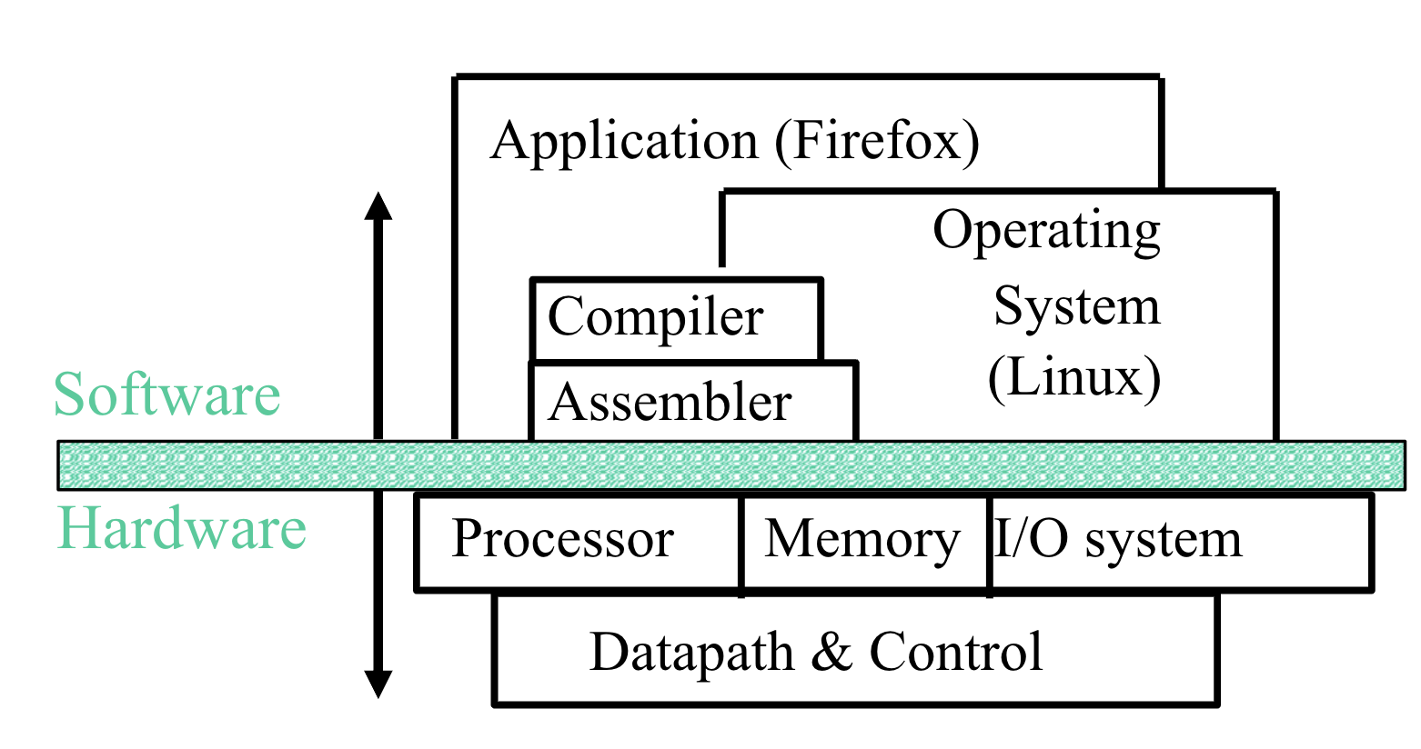
In order to get hardware to compute something, we express the task as a sequence of bits. Abstraction is a key concept that allows us to build large, complex programs, that would be impossible in just binary. Machine language, which is simply binary instructions are what computers understand, but programming in binary is extremely slow and difficult. To circumvent this, we have assembly language, which takes an instruction such as add A, B and passes it through an assembler, which simply translate a symbolic version of instructions into the binary version. While this is an improvement over binary in readability and easibility of coding, it is still inefficient, since a programmer needs to write one line for each instruction that the computer will follow. This brings us to compilers, which compile a high level language into instructions that the computer can understand (high level language $\to$ assembly language), which allow us to write out more complex tasks in fewer lines of code.
RISC-V
RISC-V (RISC $\to$ Reduced Instruction Set Computer)is an open-source ISA developed by UC Berkeley, which is built on the philosphy that simple and small ISA allow for simple and fast hardware. RISC-V is little-endian.
- Note: CISC (Complex Instruction Set Computer) $\to$ get more done by adding more sophistacated instructions (each instruction does more things, which reduces the number of instructions required for a program, but increases the CPI)
-
MUL mem2 <= mem0 * mem1$\to$ helps save memory by writing fewer lines of code (very important during 80s, not so much anymore), downside is that hardware logic becomes much more complicated
-
- Internally, Intel/AMD are CISC instructions get dividing into $\mu$ ops (micro-ops), where one CISC operation splits into multiple micro-ops.
- smaller code footprint of CISC and processor simplicity of RISC
A program counter (PC) is a special register that holds the byte address of the next instructions.
Instruction Cycle Summary:
- PC fetches instruction from memory
- Processor decodes the instruction (is it an add, store, branch, etc)
- Logically execute the instruction (logically compute x1 + x2)
- Access memory to write in result of computation
- Write back to register (x3 now contains x1 + x2)
Basic RISC-V syntax:
-
addi dst, src1, immediate$\to$ we addsrc1, with animmediatevalue (aka a constant 12 big signed value) and store it indst-
addi x1, x1, 3$\to a = a + 3$
-
RISC-V follows the following design principles:
- Design Principle 1: Simplicity favors regularity
- Design Principle 2: Smaller is faster
- Design Principle 3: Good design demands good compromises.
Simplicity favors regularity
RISC-V notation is rigid: each RISC-V arithmetic instrution only performs one operation and requires three variables. Each line of RISC-V can only contain one instruction.
-
add a, b, c$\to$ instructs a computer to add two variablesbandcand store the result ina. - adding variables
b+c+dand storing intoa-
add a, b, c$\to$ The sum of b and c is placed in a -
add a, a, d$\to$ The sum of b, c, and d is now in a -
add a, a, e$\to$ The sum of b, c, d, and e is now in a
-
Smaller is faster
Arithmetic operations take place on registers $\to$ primitives used in hardware design that are visible to the programmer when the computer is completed. Register sizes in RISC-V are 64 bits (doublewords) and instructions are 32 bits. There are typically around 32 registers found on current computers, because more registers increases the clock cycle time since electrical signals have to travel further.
Since registers have a very small limited amount of data, we keep larger things, like data structures, in memory. When we want to perform operations on our data structures, we transfer the data from the memory to the registers, which is called data structure instructions. We use a load operation ld to load an object in memory into a register. store is the complement of the load operation, where sd allows us to copy data from a register to memory.
-
ld dst, offset(base)-
ld x1, 15(x5)store the contents of address 8015 in registerx1wherex5= 8000 and15is our offset.
-
Most programs today have more variables than registers, which requires compilers to keep the most frequently used variables in registers and place the remaining variables in memory (latter is called spilling). Data in registers is much more useful, because we can read two registers, operate on them, and write the result. Data in memory requires two separate operands to load and store the memory, without operating on it. Data in registers take less time to access and have a higher throughput than memory, and use less energy than accessing memory.
Pipelining
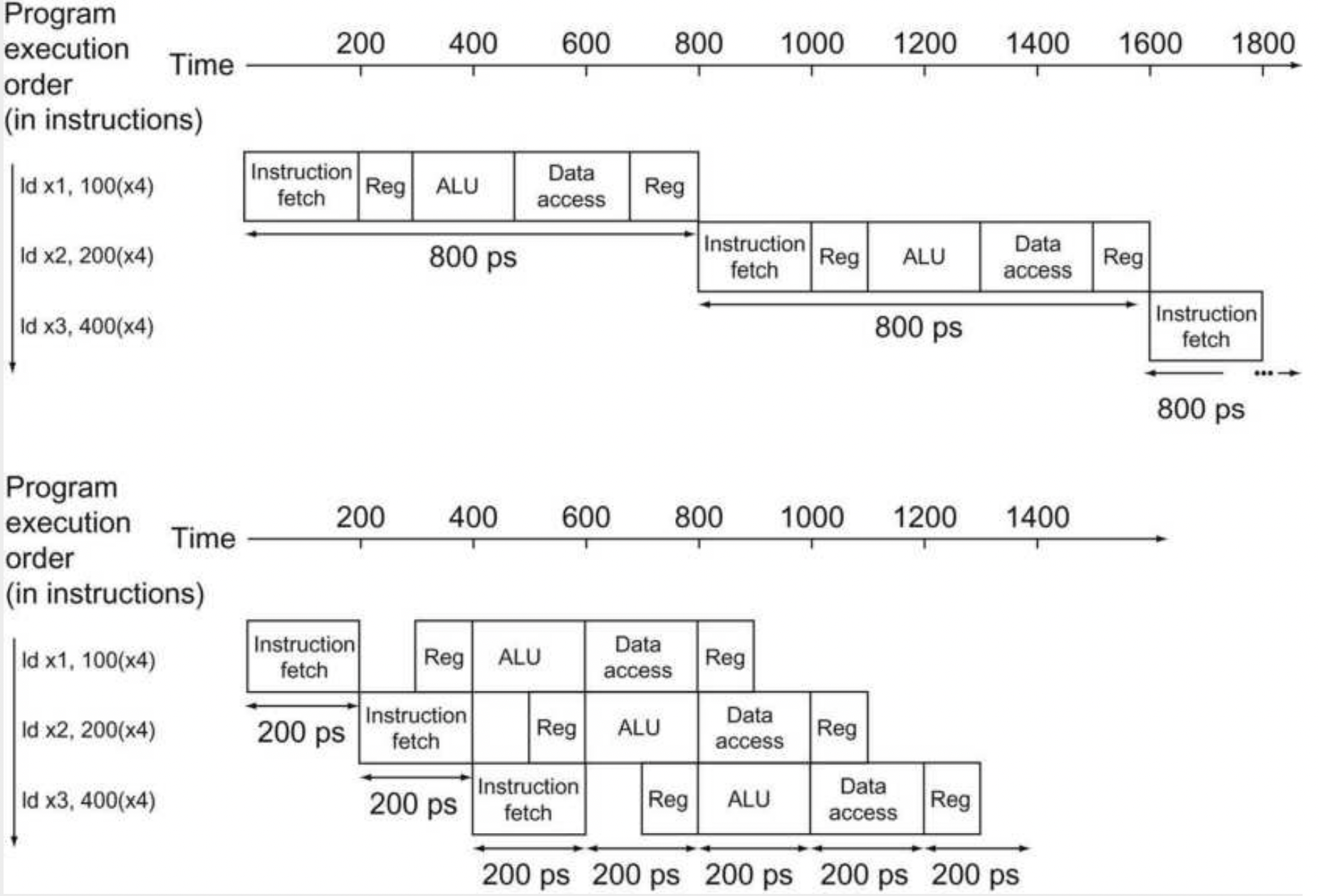
Pipelining $\to$ implementation technique in which multiple instructions are overlapped in execution (like an assembly line). We can’t improve latency but we can improve throughput. We are exploiting parallelism between the instructions in a sequential instruction stream.
-
Analogy: If we have two loads of laundry, we put the first load in the washer. When it’s done, we put it in the dryer,and we place the second load in the washer. When both loads are done we take the first load out of the dryer and we put the second load into the dryer.
- built on the idea that as long as we have separate resources for each stage, we can pipeline the tasks. Each step is considered a stage in our pipeline.
RISC-V is highly optimized for pipelining because each instruction is the same length (32 bits). RISC-V also has fewer instruction formats, where source and destination registers are located in the same place for each instruction. Lastly, the only memory operands are load and store, which makes shorter pipelines.

Here we can see an example of a pipelining process. We can see a large difference between pipelined process and non-pipelined process below.
Hazards
Structural Hazard $\to$ when a planned instruction cannot execute in the proper clock cycle because the hardware doesn’t support the combinations of instructions that are set to execute.
- Ex: If we go back to the earlier pipeline stage, if we had a single memory instead of two memories, our first instruction access data from memory, while our fourth instruction is fetching an instruction from the same memory.
Data Hazard $\to$ when a pipeline is stalled because one pipeline must wait for another pipeline to finish.
-
add x19, x0, x1
sub x2, x19, x3
- Our add instruction doesn’t write until the fifth stage, so we have to wait three clock cycles to save our value. We have a dependence of one instruction on an earlier one that is still in the pipeline.
Forwarding (bypassing) $\to$ is the process of retrieving the missing data elements from internal buffers rather than waiting for it to arrive to the registers or the memory.
Control Hazards (aka branch hazard) $\to$ when the proper instruction cannot execute in the proper pipeline clock cycle because the instruction that was fetched is not the one that is needed; that is, the flow of instruction addresses is not what the pipeline expected.
- We’re cleaning dirty football uniforms in the laundry. We need to determine whether the detergent and water temperature setting we select are strong enough to get the uniforms clean but not so strong that the uniforms wear out sooner. We need to wait until the second stage to exaine the dry uniform in order to determine if wee need to change the washer setup or not.
- Stall $\to$ operate sequentially until the first batch is dry and repeat until we have the right formula. Generally too slow to be used in practice.
-
Predict $\to$ If we’re sure we have the right formula to wash the clothes, we can just predict that it will work and wash the second load while the first one waits to dry.
- Branch prediction $\to$ we can assume a given outcome for a the conditional branch and proceed from that assumption rather than waiting to ascertain the outcome.
Superscalers $\to$ Superscalar processors create multiple pipeline and rearrange code to achieve greater performance.
Cache
In order to speed up memory access, we employ the principle of locality, where programs only need to access a relatively small portion of address space. The big idea of caching is that we rely on the principle of prediction. We rely on the information we want to be in the higher levels of our memory hieararchy in order to speed up our computation.
- Temporal locality (time locality) $\to$ items that are referenced will probably need to be referenced soon.
- Spatial locality (space locality) $\to$ items that are referenced, its neighbors (of addresses) will probably be accessed soon.
- Memory hierarchy $\to$ multiple levels of memory with different speeds and sizes. Faster memory is more expensive and thus smaller.
Main memory is implemented in DRAM (dynamic random access memory), where levels closer to the processor (caches) use SRAM (static random access memory).
-
Cache: $\to$ small amount of fast, expensive memory
- L1 cache: usually on CPU chip, 2-4x slower than CPU mem
- L2: $\to$ maybe on or off chip
- L3: $\to$ off-chip made of SRAM
- main memory $\to$ medium price, medium speed (DRAM)
-
disk $\to$ many TBs of non-volatile, slow, cheap memory
- SRAM has fixed time for data access, while read and write access times may differ
- DRAM uses a two-layer decoding, which allows us to refresh an entire row (which shares a wordline), and have a read cycle followed immediately by a write cycle.
-Direct Mapping $\to$ each memory location is mapped to exactly one location in the cache. (Multiple memory locations may map to the same spot in the cache). We use a set of tags, which contain the address information in order to identify whether a word in the cache corresponds to the requested word, since multiple locations in memory map to the same location in cache.
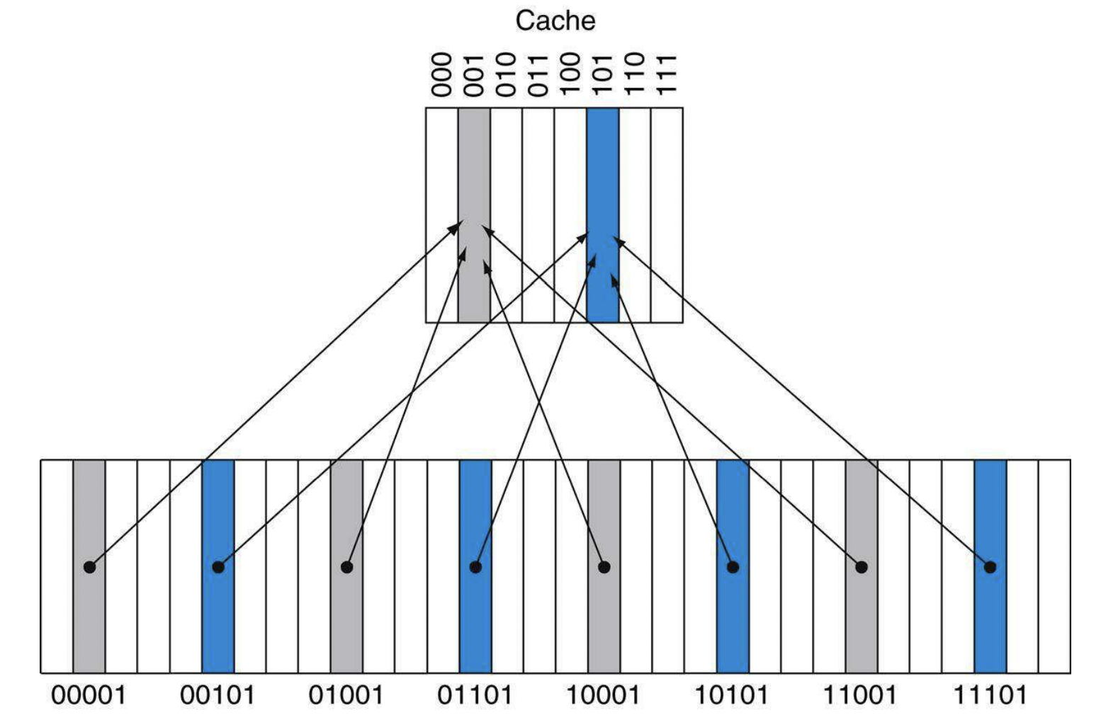
-
miss penalty $\to$ the penalty is determined by the time required to fetch the block from the next lower level of
the hierarchy and load it into the cache.
- A simple way of dealing with a cache miss is where we stall our pipeline, while we wait for our data to be retrieved from memory.
Handling Writes
write-through $\to$ write cache and through the cache to memory every time. A write buffer updates memory in parallel to the processor. Simple and reliable, but slower.
write-back $\to$ We write the information only to the block in the cache. We only write to memory when our information is evicted fropm the cache. We have a dirty bit that indicates if the data is modified(dirty) or not modified(clean). We only write back to memory when the data is dirty.
Multilevel Cache
Two approaches to improving cache performance:
- We reduce the miss rate by reducing the probability that two different memory blocks map to the same cache location.
- We reduce the miss penalty by adding an additional layer to the memory hierarchy.
Traps and Interrupts
An interrupt is caused by an external factor to the program.
- This ends up trashing the cache: extremely expensive
An exception is caused by something during the execution of the program.
A trap is the act of servicing an interrupt or an exception.
- Trap handling involves completion of instructions before the exception, a flush of current instructions, a trap handler, and optional return to the code.
Virtual Machines
Virtual machines are enabled by a VMM (virtual machine monitor), where you have an underlying hardware platform that acts as a host and delegates resources to guest VMs.
In order to virtualize a processor, a VMM must have access to a privileged state, in order to control I/O, exceptions, and traps.
VMs are useful for 3 reasons:
- 1)Increased Protection + Security: Multiple users can share a computer, especially useful for cloud computing. Better isolation and security in modern systems.
- 2)Managing Software: provides an abstraction layer so that a machine can run any software stack
- 3)Managing Hardware: allow separate software stacks to run independently and share hardware
Virtual Memory
Virtual Memory $\to$ is a technique that allows us to use main memory as “cache” for secondary storage. Virtual memory gives the illusion that each program has access to the full memory address space. The virtual memory implements a translation from a program’s address space to physical addresses. This helps enforce protection of a program’s address space because it stops programs from accessing other program’s memory. Since we map a virtual address to a physical address, we can fill in “gaps” within our physical memory.
Virtual memory also allows us to run programs that exceed our main memory.
How does virtual memory work?
- We have a page (virtual memory block). We can use address mapping, where our processor produces a virtual address which gets translated to a physical address.
-
Page Table $\to$ a table that contains the virtual to physical address translations in a virtual memory system. The table that is stored in main memory, and is indexed by a virtual page number. Each entry in the table contains the physical page number for the virtual page that is in memory. Each program has it’s own page table, that maps the virtual address space to main memory.
- In order to access a byte in a page table, we need to perform two lookups: one for the page-table entry, and a second for the byte.
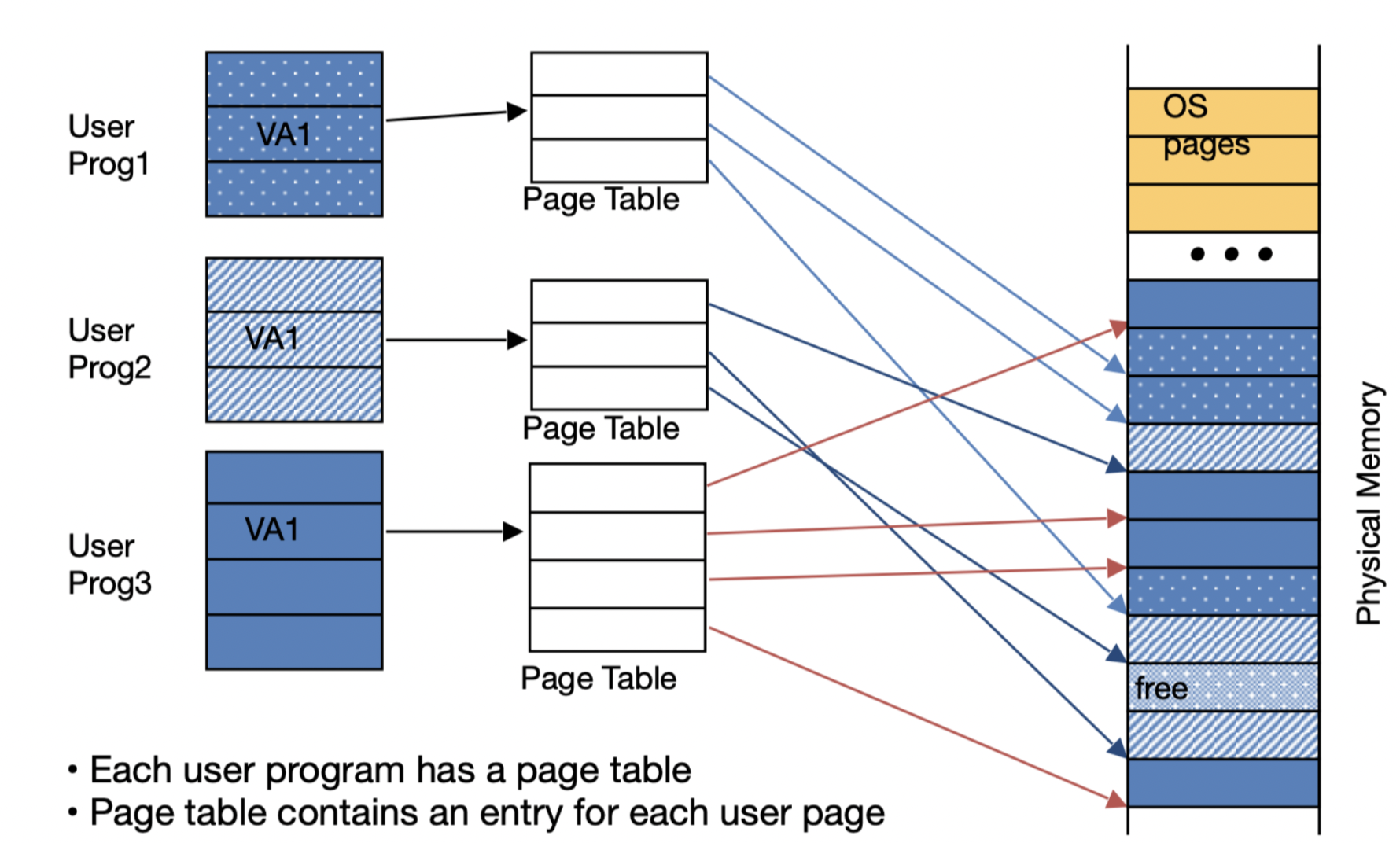
- We have a page fault when our virtual memory misses. Page faults are very costly, a page fault to disk could cost millions of clock cycles. When this happens, our OS is responsible for replacing a page in our main memory (assuming all pages in main memory are in use). Generally we use an LRU method (least recently used), but we only approximate the LRU, which is computationally much cheaper.
- The OS replaces a page in RAM with our desired page in disk. If our page is dirty (meaning that there isn’t copy in disk), then we need to write it to disk. We the update our page table to reflect our changes.
- Page faults are so painfully slow (because retrieving from disk), that our CPU will context switch and work on another task. About the slowest thing that can happen.
-
We have a swap space where we have space on the disk stored for full virtual memory space of a process.
- Each page entry is 8-bytes in RISC-V, this means that it could take .5 TiB to map virtual addresses to physical addresses.
- 1) Keep a limit register that restricts the size of the page table for a given process.
- 2) We divide the page table into two: we let one grow from the top(high address) toward the bottom, and one grow from the bottom(low address) toward the top.
- doesn’t work well
Virtual memory works great when we can fit all our data in our memory, or most of the data fits into memory, with only a little needed to go to disk. But as soon as our working memory exceeds our memory, we have thrashing, where we need to repeatedly move data to and from disk, which causes a huge decrease in speed.
TLB
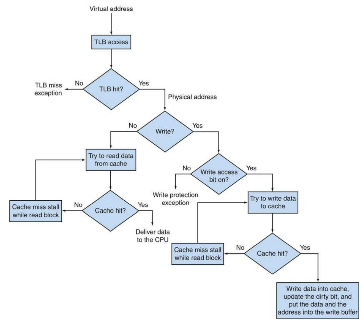
Translation-lookaside buffer $\to$ a cache that keeps track of recently used address mappings to try and avoid an access to the page table. On reference, we lookup the virtual page number in the TLB. If we get a hit, we use physical page number to form the address. If we get a TLB miss, we check if it’s just a TLB miss or a page fault. If the page exists, we load the translation for the page table to the TLB. If it’s a page fault, then our OS needs to indicate an exception. Generally these are resolved by bringing in the data from disk to physical memory, where we set up a page table entry which maps the faulting virtual address to the right physical address.
- The TLB is a subset of the page table, which acts a cache for the most recently used mappings.
- If our cache is virtually addressed, we only access the TLB on a cache miss.
- If the cache is physically addressed, then we use a TLB lookup on every memory operation.
- We generally have 2 TLBs: iTLB $\to$ for instructions, and a dTLB $\to$ for data.
For best of both worlds, we use ViPT (Virtual Address, Physical Tag) $\to$ we lookup in the cache with a virtual address and we verify that the data is right with a physical tag.
- We do a TLB translation(use virtual pages to index the TLB) and a cache lookup(use page offset bits to index the cache) at the same time.
- If the physical page (from TLB) matches the physical tag (from the cache), then we have a cache hit.
Compilers
constant folding $\to$ compiler optimization that allows us to evalue constant expression times at compile time, rather than runtime.
-
int i = 10 * 5$\to$ compiler will calculate thati = 50.
inlining expansion $\to$ compiler optimization that replaces a function call site with the body of the function.
Differs from JIT (just in time compilation), which compiles programs during execution time, which translates bytecode to machine code during run time.
Preprocessor $\to$ responsible for removing comments, replacing macro definitions, and preprocessor directives that start with #.
Compiler:
- Front End: $\to$ build an IR of the program and build an AST(abstract symbol tree).
- Lexical Analysis: takes the source code and breaks them down into tokens.
- Syntax Analysis: Build a parse tree that takes the input tokens and builds a tree that represents the formal grammer rules of the compiled language
- Semantic Analysis: Add semantic information to the parse tree and build the symbol tree.
- Middle End: $\to$ optimize the code irrespective CPU architecture.
- Analysis: Build the control flow graph and the call graph.
- Optimization: Optimize the code $\to$ inline expansion, constant folding, dead code eliminations, etc.
- Back end: $\to$ CPU architecture specific optimization and code generation.
- machine specific optimizations
- Code Generation: convert the IR to machine language.
LLVM
LLVM is a modular architecture, that unlike the many different compilers that had optimizations that would only work with that particular compiler, LLVM provided a backbone which made extending custom optimizations much easier.
-
IR (intermediate representation) $\to$ the phase between C code and assembly. Files go from
foo.ctofoo.ll. Then,fool.llwill keep being transformed into itself through LLVM until LLVM has no further optimizations to apply, which then will be converted to assembly code. The goal of this is so that the LLVM IR code will be the same across languages, and then transformed into specific assembly language.- Swift has SIL(Swift intermediate language) which is a second intermediate representation (goes before regular IR). This allows Swift to recieve different kinds of optimization, which allows a higher level language like swift to benefit from further optimizations.
- During compilation, variables are stored in SSA (static single assignment) form.